


The industry wants to save energy in utility air screw compressors and is trying different ways to implement the same, says Ashok S.
For the given demand for air volume, the industry has planned around two-thirds to be supplied by fixed load of compressors. The balance is to be supplied by the Variable Frequency Drive (VFD) modulating air compressor.
The air screw compressor loses energy in generation in the compressor house, in the distribution at the compressed air header and branch piping, and in usage. This is in two ways that is machine usage and air leakage in the final pneumatic control elements inside the machine.
Let us discuss the compressed air flow, generation pressure and dynamic variations in the header pressure which prompts the need of VFD in screw air compressors.
Why is there need for VFD in the Screw Air Compressor Utility?
VFD is needed for the compressor system since the compressor discharge pressure varies depending on the air flow demand from the process. Compressed air pressure is a dynamic variable, hence VFD is applied to the compressor control to steady and optimise compressor discharge pressure or header pressure.
1. Take the case study of 45 KW air compressor run for 24 hours a day. The industry keeps the compressor load-unload pressure band practically in the band 0.5 Bar to 2 Bar say, between 6 to 8 Bar. To suit process demand, the compressor loads and unloads frequently round the clock.
2. The industry first wants to minimise unloaded compressor working hours, so it is trying to operate compressor load-unload ratio at 80:20 economically and monitoring the same. It routinely changes load-unload pressure settings to achieve maximum loading hours and reduce daily unload hours to a minimum since unloaded power consumption is 40 per cent of rated compressor KW.
3. So, to save, VFD is retrofitted. This is done by narrowing the pressure band to pin point around 6.5 Bar, earlier set at 6.5 to 7.5 Bar. The VFD saves in unloaded power. Hence, on reduced pressure by VFD, the user saves the compressor KW by reducing from 7.5 to 6.5 Bar. But measured savings are less. BEE guidelines indicate 6 to 10 per cent power savings for each bar pressure reduction from 7 to 6 Bar.
Why is the VFD in Screw Air Compressor not effective fully?
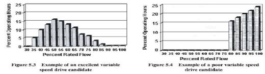
VFD to the existing screw air compressor is an example of poor variable speed drive candidate. The diagram above and the details below clearly show why VFD could not be effectively be utilised for most of its operating hours per day.
1. The chart above is of two types of VFD working. One is an excellent variable speed drive piece because the per cent loading in the 24-hour cycle a day is part loading where the working efficiency band is more. The same VFD will be a poor variable speed drive if the loading is near full load for most of the 24-hour cycle.
2. For example, in the 45 KW screw air compressor, the compressor OEM gives the ratings as motor KW, air delivery CFM and max working pressure in Bar (as shown in the compressor name plate below). But in the field, the compressor rated at 8 Bar takes the full power input at 53 KW, even when working at 6.5 Bar pressure. If the same compressor is worked at pressure of 8 Bar, then its input power shoots more than 60 KW. So the rated input KW is much more than the input rated KW of compressor motor, comparing to the name plate specs. Here, the name plate does not include the post air cooler fan KW in the specifications. So the name plate must include total motor KW used inside the compressor hood to deliver output.
3. So on a scale of 10, invariably 9 industries consume more than the rated KW of compressor, even when operating at a pressure below the rated pressure. First, why does this happen? The compressor Original Equipment Manufacturers or OEMs can only answer questions on excess consumption with reference to the name plate and give their recommendations to improve compressor energy savings using VFD.
4. So the point of putting a VFD in a fully loaded compressor will increase overall KW consumption, since the VFD consumption at full load is also added. Since the VFD cannot regulate pressure pin-pointedly, the compressor at the operating pressure consumes the rated compressor plus VFD package power.
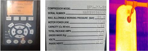
10 Bar rated compressor, VFD operated at 7.5 BarandCompr Name Plate / AIR Receiver IR image
5. So VFD cannot function efficiently during loading. On a 45 KW compressor, the unloaded power being 20 KW, VFD action will give around 5 KW savings. So the VFD's energy savings for 4 unloaded hours/day is around 20 units on compressor consumption of 1,100 units. This low savings plus reduction in loaded KW due to reduced pressure and load variations in the process side results in less KW consumption, achieved practically by VFD.
6. Compressor OEMs hold that the compressor motor is rated with service factor of 1.2. So, cyclic overloading to 120 per cent will not harm their motor. But it is a loss since any motor operated above the ratings, and operated 24 x 7, eats into its efficiency and accelerates ageing.
7. In many compressors, if air intake filter is choked or if it receives air hotter than 5 *C inside the hood compared to surrounding ambient temperature in the compressor house, this is also one of the factors for the VFD to fluctuate more in the closed loop pressure control of header pressure. So we need to monitor air intake delta P and preferably locate the filter outside the hood or house to allow the compressor to suck cool dry air instead of hot harsh stale air.
8. The screw compressor is operated in load-unload mode based on the output pressure. This pressure is measured using a pressure sensor located immediately at the outlet inside the hood. The location of pressure control sensor makes the compressor VFD ramp up and ramp down faster due to pulsating air pressure instead of streamlined air pressure. This is due to the post air cooler, located near the sensor inside the hood and the micro filters fitted in the CA lines in between the hood and compressor. For the VFD operation, it will work smoother if the same load-unload pressure sensor is relocated to the air receiver.
How can the industry save energy in VFD run compressors?
1. We need to operate 8 Bar rated compressor at, say, less than 6 Bar through VFD for efficiency to save energy through the 24 hours/day cycle. First try to reduce compressor discharge pressure to the minimum possible say, less than 6 Bar by investing in air receivers and reducing the line pressure drops in the distribution in header and sub-header areas.
2. Air-consuming machine OEM who demand minimum air pressure requirement for their machines, have started reducing demands from the rated 7 Bar to 5 Bar. So it makes sense to speak to the equipment vendor on how to reduce machine pressure settings from 7 Bar to the minimum 5 Bar. Dimensions of pneumatic actuators can be changed to match the required force and pressure as Kgsc equals to 1 Kilogram force to act on the given 1 sq cm area?
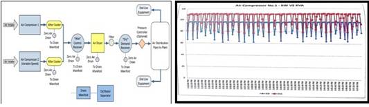
Wet and Dry Air receivers / 75 KW rated compressor consumes 95 KW, cyclically fluctuates due to wrong sensing.
3. Invest in air receivers as they do not involve running costs. It is healthy for the compressor and dryer to operate with buffer tanks. Provide a wet type air receiver to dampen the compressor discharge pressure pulsations and locate this receiver between the dryer and filter package. Provide dry type air receiver after the dryer and filter components at the tail end of compressor house piping header. This will be a buffer tank between the process and the compressor.
4. Relocate the compressor
load-unload pressure control sensor to the dry type final air receiver in the
compressor house and wire the same to the compressor panel. This relocation
dampens the pressure pulsation happening due to the existing location of the
pressure control sensor in between the compressor discharge and dryer. The
input pressure variable taken from this sensor will be steady here after, as
the receiver volume dampens the pulsations and will truly reflect the steady
compressed air header pressure demanded by the process utility. This also
increases the efficiency of VFD run as the pressure impulse spikes are
flattened now.
How can
the compressor be efficiently run?
1. Purchase a higher pressure
rated compressor say around 8 to 10 Bar. Deploy it not at full load but at part
loading on the efficient band advised by the compressor OEM.
2. When we plan to buy say, a 45
KW compressor, it is logical to ask the compressor OEM to give 55 KW IE3 motor
to suit this package instead of 45 KW + SF 1.2 It is always efficient to
operate the compressor motor at around 80 per cent loading in the maximum
loaded conditions. Compressor OEMs can be consulted to confirm the motor
related savings.
3. Plan to have multi function
energy meters for each compressor to show the instant KW, and cumulative KWH in
run hours, KWH in load hours, KWH in load and unload hours separately, apart
from the load and unload Hours recording.
4. Have digital/analog Pascal
gauge with alarm setting to measure air intake pressure differential across the
filter. By routine monitoring and maintenance, if we keep air intake Delta P to
be minimum say around 100 mmWC, this ensures air is freely delivered at the
intake. VFD will pulsate the output more if the intake filter is choked and we
don't' get the required Free Air Delivery (FAD) at the mouth of the compressor.
5. Also, to have digital RTD based
temperature gauge at the final air receiver to show the healthiness of
compressed air treatment sub systems like post air cooler, ref dryer etc.To
have digital pressure display and remote indication and alarm of the final air
receiver and transmit the same to User. The above two parameters show the
healthy steady workings of VFD compressor.
6. On 1000 KVA demand sanctioned
to the industry, it is not logical to set the OLTC (On Load Tap Charger)
transformer at 430 volts just for the sake of this overloaded 45 KW compressor
running at the tail end. If the compressor motor rating is chosen as 55 KW,
then the whole industry can be operated at 400 volts+ because, in many industry
segments, average loading of the all motors is around 75 per cent only. The KW
consumption is less and Kilo-Volt-Amps (KVA) demand is less in 400+ volts range
instead of 420+ volts now in any motor system operating at around two third
loading. An overloaded compressor motor consumes more KW when the voltage is
less than 400 Volts instead of 420 Volts. So, aim for higher efficiency by
motor loading around 80 per cent.
7. Avoid putting capacitor bank
say at 25 KVAR (Kilo-Volt-Ampere-Resistance) in the compressor house SSB,
having 3 compressors at 45 KW rating, out of which, one compressor is having
VFD. It is better to put lagging capacitor at the individual compressor panel
for individual load end compensation and no capacitor bank at the incoming of
VFD compressor SSB. This cap bank at VFD incoming SSB panel will amplify the
KVA demand and multiply the harmonics generated from VFD incoming.
8. Some industries where the
compressor is the main utility consuming two-thirds of power in the industry,
consumption is forced to go for active harmonic filters in the power house,
since they had already installed those capacitor banks at the incoming of VFD
compressors. Why increase harmonics and KVA at load end by the incoming
capacitor banks at their SSB and later try to reduce the same at the power
house with higher size of AHF? It is better to house arrest the harmonics
within the compressor. THD can reduce by one-third by putting line reactance
choke at the incoming of the VFD driven compressors.
9. Level sensing automatic drain
valve along with Y type in-line strainer (for daily cleaning) to be fixed at
the bottom of air receiver. Timer based drain valves leak out the air only,
instead of water. One reason for pressure drop in the compressed air header is
the ref dryer not functioning optimally. Water trace ingress in the dry air
assembles dust micro particles and obstructs the X secion of pipes at the
joints, causing pressure drop.
10. Talk to the
Air-consuming-machine OEM to retrofit say a 4 inch dia 20 feet length PPR pipe
near / bottom or top of machine and this can act as a buffer 50liter tank. We
can avoid a pressure booster if this buffer air bottle is installed in each of
the machine. To fix this retrofit, inside the machine in the line, after all
the Pressure Regulator output is done; and this buffer pipe will act as
Regulated Air supply displayed with pressure gauge, to the machine always
in-line with machine feed air. This air sub regulated pressure header at
machine to be visible, and easy for access and monitoring, during daily
routines.
Segregate
cleaning air foam process utility
Coming to the compressed air
pressure fluctuations happening inside the production area, one of the reasons
is that the cleaning air is taken from the same compressed air main header. A
bluntly open quarter inch sized cleaning air hose releases air at the rate of
100 CFM, the cubit feet per minute thus consuming 20 units per hour. Some
industries use half inch sized air hose that too frequently during the day time
at multiple cleaning locations. Make, efficient practicing of air blow guns
that too with COANDA type energy-efficient nozzles. Now we understand why the
compressed air header pressure widely fluctuates heavily. This causes low
pressure alarm at the process and the compressor VFD to put to more strain
because of heavy blowing out mainly.
Separate air receiver for Cleaning
App + Pipe Line Regulator/10 Feet Cu Tube as fixed regulator
1. To solve this cleaning air
application which heavily withdraws air in bulk, it is mandatory to install a
separate air receiver near the cleaning hose area, sized to the one-at-a-time
cleaning application but not to allow multiple cleaning at the same instant by
many users. The air receiver will house only 4 Bar rated air pressure instead
of 7 Bar used now. This is done by sized spring loaded air line regulator fixed
at the feed end of the receiver and this will maintain the air receiver at 4
Bar only.
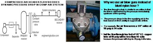
2. At the point of use of 7 Bar
air line, make a spiral tubing around 10 feet of quarter inch size copper tube
and then give output for cleaning. This will consume only 40 CFM at around 3
Bar at the outlet point. This is fixed and sustained pressure reduction and the
same is sized to the cleaning application without choking, but steady and low
flow cleaning is done here.
3. Heavy pressure drops and
fluctuations in compressed air header pressure happen due to:
a) Sudden exhausting of air flow
during heavy blowing cleaning application
b) Frequent operation of pneumatic
cylinders fitted in the equipments. These will consume more when electro valves
fitted on those pneumatic cylinders bleed outside.
c) Air leakage flow through pipe
fittings, hose joints, etc are firm but still pressure drops steadily.
So, VFD retrofitting to any screw
air compressor will result in good savings if operated in part loading, of say
two third loading of compressor rated KW. To achieve energy savings in VFD we
have to operate the VFD to give smooth input, slow ramp up and down output, and
range of VFD to match compressor package KW.
Ultimately in any system, energy
saving by VFD is possible only when the compressor, compressed air and
compressed air treatment parameters of sub-systems like dryers and filters are
healthy. When the laminar and streamlined energy flow by way of steady air
pressure is obstructed abruptly inside without your knowledge, then you face
energy loss in the compressor house and internal installations, in the
distribution piping system, and in usage points.
Most buyers pick up the most
efficient compressor, sub-systems and the total package above the current
industry compressor running norms. Yet, after spending a neat package on the
compressor, they neglect to ensure best installation practices. Many a good
compressor system operates poorly for life due to wrong installation.
Inefficiency starts from the date of installation and increases, resulting in
less CFM output per running KW and frequent breakdowns. So, it is important to
clear the defects within the system by monitoring and predictive methods.
Adding a VFD to an unhealthy compressor and compressed air system will bring
the system down further and cut into expected energy savings.
About the
author:
Ashok. S is a BEE-accredited energy auditor from Coimbatore


Comments